Sunday, March 20, 2011

Perfect word for the builder.

I heard some calling the word "Boob" a perfect word...perfect?


Can u get it?
Profile, Body Plan and Half Breadth?

Now you'll see cause you're a boatbuilder.

Sunday, March 13, 2011

Composite Boatbuilding 2

Setting Up the Frames

For the posting with bigger photos, follow the link below.
http://yate.tistory.com/entry/Composite-Boatbuilding-2

1.Setting Cross Spalls

Cross spall is the part which holds each frame on the Strongback(Cleat?) and coincides with each station lines on the floor. To set up the cross spalls, we need to decide some conditions as below.

* We're setting
- numbered face of each frames heading backward(astern).
- Frames before station line for STN.0 to STN.12(Widest Beam)
- Frames after station line for STN.13 to STN.15

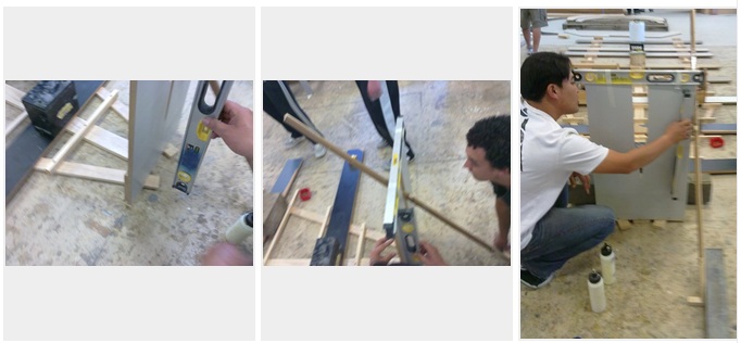
To set the cross spall, station line must be marked on the Strongback(Cleat?) but station line is marked on the floor. So we need to transfer those lines into Strongback with accuracy. Photo below shows how we transfer the line vertically.


With two square rules lined with station line on the floor and a Straight Edge, you can transfer station line from the floor to Strongback.

For STN.0 to STN.3, we used whole piece for cross spall, but after that, cut the timber to small pieces to save plank(I guess) (Photo below)


Also, we used glue(PVA) and screw altogether to set up the cross spalls firmly.


While we were fixing the cross spalls, we used straight edge again to make it quite accurate, but later some of the the cross spall has been slightly moved and we fixed it.(Photo above)


2.Setting up STN.0 and STN.1 Frames.

In setting up the frames, most important thing is level(vertically and horizontally). For level, we are going to use device called "Dumpy Level".

But to use Dumpy Level, it must fixed onto somewhere with clear view of target and no one cna easily move it.


After we set its position, we made three wood blocks with a 10mm hole in which spike of tripod fitted then glued it onto floor with some weight on it. So, another 24 hours to use it,

So, for th STN.0 and STN.1, we used conventional way, level, level and level!!!

And before we start it, we also made jig for 15 degree wedge and wedges using the jig.
PHOTO INSERT Here!!!!!

STN.0

We set the frame onto STN.0 spall and made its center line is on the Centre Line of the boat. Then, we placed a level on top of the frame and wedges on each side. By pulling and pushing the wedges, we set the horizontal level. Once horizontally leveld, then, we fixed the frame onto the cross spall using screw driver. Then, we pulled out those two wedges and glued them. Then, put them bakc uder the frames and snap off the rest of wedges. So, now it's horizontally leveld.
  

Then, we need a long piece of brace to hold vertical level position. The brace must be fixed onto floor or somewhere.
With brace attached to the frame, using another level vertically we set its vertical level. When it's leveld, we fixed the brace with some weights.(We didn't have any glued block on the floor for the use)


So, now STN.0 is vertically and horizontally levled.

STN.1

Since Chine is also Water Line, Chines of all frames must be at the same level and we are using this to set the STN.1

This time we need three leves, two metal rules and two wedges.

Set the STN.1 on the station line and Center Line must be matched. Then, clamp one metal rule horizontally right on the Chine line of the STN.1 and another metal rule on the STN.0 exactly the same.

Then place a level on top STN.1 and two more levels on each side of metal rules in the crossing way to another.

Using wedges, try to find a position where all the bubbles in three levels are in center.

Once it's done, fixing process is the same.
- Fix the frame with screw driver onto the cross spall
- Pull out the wedges and make'em glued. Put them back and snap off the rest of wedge


The rest of Frames with Dumpy Level.

How to use Dumpy Level.
First we need to level the device. The one we used has three knobs to adjust its own level.
When it's leveled, aim a target on which we could mark comparison level then mark the comparison line on the traget.
So the observer gives directions on where to mark. The reason why we mark the comparison line is when the Dumpy Level has been moved by accident, we need to set the same level again. For this reason, comparison line must be marked on somewhere easily not moved.


Leveling using Dumpy Level


Then, we need to get two long sticks called "Story Rod". We clamp it to each side of frames right above of Chine.(To be matched on Chine).  Then we mark the same level on the stick as comparison line. Since the Chine on all the frames are at the same level, a distance from Chine to marked line of Story Rod in one frame must be same as in other frames too.

So we are using this to level all the other frames.


1.Mark the comparison line on masking tape using Dumpy Level(Left)
2.Clamping Story Rod to the frame(Right)
3.Mark the same level line on the Story Rod(Center)


When you look into the scope, you see the marked line is a bit higher than level. So observer gives direction to lower the frames a bit.


While we are leveling and setting up the frames, it must be stay leveled. So we attached temporary brace on top of frames and it will be replaced with stronger brace.
1.Temporary brace is placed on top of frames(Left)
2.Cutting out beveled shape for stronger brace for later use.(Center & Right)


Differnt shapes of cut off for brace - Straight Brace(Rectangular) and Angled Brace(Beveled)


Temporary braces were replaced with stronger braces. Straight brace and diagonal brace were attached to the frames and also to the floor with glued block.


So all the frames and braces are completed.

Saturday, March 12, 2011

Composite Boatbuilding 1

Composite boat building.

For the posting with bigger photos, follow the link below.
http://yate.tistory.com/entry/Composite-Boatbuilding-1


1.Frame Design


Picture below is one of frames and explanation how we got it follows.

From the picture above, B is deck line and to get "a"(below), draw a dicretionary line A(above). Now distance between A & B(Deck Line) makes "a".

For b, all the frames from STN.5 to STN.15 has fixed value of 830(from C.L) which is longer enough so it could sit on C.

Those frames from STN.0 to STN.4 have values of distance between A & B(Deck Line) as "b".

And straight line connecting a and b(below) starts from CHINE level but there are some irregulars on STN.5,6,7.(They starts from under CHINE level and I don't know why but not important, I think.)


And draw a line under canoe body(In this case, the line is 470 down from CHINE) and then we get  enough space of frame to join. All frames have fixed value of 470(CHINE to bottom) but different values on CHINE to SHEER.


2.Frame Cutting

When we got there at workshop, only one frame was left to be processed through CNC(Computerized Numerical Control).

To get it processed through CNC, CAD file(.dwg) must be saved as .dxf(Not Sure!).

But, the machine we used is 3D machine and AutoCAD drawing contains only 2D information. It doesn't have any information on how thick those frames are. Q.So do we need to add 3D information? or ??

Video below shows how we made frame using CNC machine and it's quite noisy, be careful while watching.


CNC machine has vacuum holder and it changes its tools automatically.
When it's done, we make holes through its cut off mark and using router-looking tolls, trim and finish it.

3.General Outlook of the Boat(or Plan)
* LOA: 5500
* Beam: 2407(at STN.12)
* 16 STNs.(0 to 15)
* C.I: 366.66
* Sailboat with center board(no fixed ballast keel)

4.Setting Up the Strongback(Cleat??)

[Half Breadth]

If there's any other word to describe those woods(C) on which frames are set, please let me know.

Picture above shows Strongback plan. Frames from o to 5 sits on two angled beams and the others are on straight beams.

1st. Clean up the floor and surroundings.


2nd.Drawing Datum & other lines.

We need to draw C.L, Stronback(Either its center line or its outside) line and Station lines.

- Drawing Center Line using metal frame with straigh edge.
- Draw Strongback lines which are parallel to C.L and draw angled front strongback lines.
- Draw AP and FP
- Setting up two tape measures on straight Strongback lines.

* When we were doing "Dory", we used a tape measure and common interval altogether to reduce measuring error.(Settig up tape measure-->Mark stations using tape measure-->Mark stations measuring Common Interval from each station). But this time, Common Interval is 366.66 and its unmarkable with human eyes and hands. So we used distance from AP(or FP) to each station to mark station lines using two tape measures.

* And also using trammel arm, made it sure that it is perpendicular to C.L and Strongback line. But to use trammel arm to get perpendicular station line(Need half length of each station), we still need Common Interval, in which there are some discrepancies.

--> Since we are not using under decimal C.I and also impossilbe to use it, we measure each station using distance from F.P or A.P. From this, we can get C.I from it and it has slight discreapancies to make up under decimal values.
367 / 366 / 367 / 367 / 366 / 367 /367 / 366 / 367 / 367 / 366 / 367 / 367 / 366 / 367  . So use this value to get perpendicular line, altogether with distance from F.P(or A.P).


3rd. Cutting Strongback
 

4th. Fixing Strongbakc to the floor

Since we decided to use "no more nails" on the floor, we used adhesive called liquied nails and it's just like using silicon sealant gun. Before we glue center piece of Strongbakc, if center line is marked on the piece, that would be much easier for later job.
 

5th.
It's taking approximately 24 hours to be completely dried up and need to put some weight on the Strongback. And also if we knew about the position where diagonal brace would be jointed on the floor, we could glue it altogether  but we did it later.
  
5.Frame Joining.

While they were working on Strongback, the other group were working on joining the frames.
1st. Gusset Cutting.

Gusset is name of the part which holds frames together.
  
We made all the gusset all 500 width(length) with differnet height depending on its frame.


2nd. Joining Floor Setting.
  

We did clean up on the floor and set the kind of bonding jig using two straight metal frames. Those two metal frames must be joined(met) at right angle. To make it sure, we used metal square rule and Pythagorean theorem which Chris told us about. But it turned out that we screwed in joining. There were consideralbe gaps between frame parts and screwing position was not proper.

So the next day, we tore apart all the frames and did it again. This time, we added more wood block(stopper) on two metal frmaes so that it doesn't move at all, used human weight on frames to hold it firmly and moved screw  position.
  
While we were joining the frames, we could do it well organized way. While some of us were gluing and screwing and the other were sanding the surface and set it in order and so on. So there was no time wasted, I think.

Monday, March 7, 2011

Instant Recap, 7 March 2011

* Boat Spec.
- Designer: Rob Shaw
- LOA: 5.5M
- BEAM:2.4M
- Material: Westren red cedar

* Terms
Composite / Gusset / CNC / PLUMB & RAKED(Bow Styles) / FEMALE MOLD / VEE / SHEATING
PEEL PLY / SUPERSTRUCTURE / GIRDERS / FILLER COAT / COCKPIT

Small Craft Building - 1.Preparation

After 2 weeks break, we started builng a small boat called "Dory".


1.Team Up

Before the break, all of us teamed up and that made us all 3 teams. Each team has 5 team members except "the A team" which has 4 members.

2.Discussion

After we teamed up, we had a discussion on some issues from  the project and team working and Sevastien made a short presentation. It was mostly about work code - Punctuality, Safety, Cooperation and Attitude things.

3.Planning

* Cutting List


We completed the list above as a cutting list. But I think it's more like a parts list because some parts in the photo needs more process than cutting. So if we knew that how those parts are made, then, we could have more detailed cutting list.

And I think we missed 2 oars in cutting list above.


* Project Management(PM)
As we all know that time is money in the project, time managment is quite essential and important.
For good Project Management plan, we need to find out some information like these.

- What parts do we need?
- What processes do we take to get the part?
- How long does it take to process the part on average?
- Is there any co-relation or sequential order between process?

These must be the very basic for the planning. But, thing is that we just started the building and we don't have any vague idea on those informations. So we skipped the PM thing.

But I did simplified PM plan for example since we've gone through some process in the project and it's below.

I am still working on this and at last posting on Dory, I will update plan with estimation of each working hours(Skilled and no screw up basis).

Link to Excel file.
https://spreadsheets0.google.com/ccc?hl=en&key=tcKnD-oz-LyNdZ4Ywnv2hpA&authkey=CJ7G4eEM&hl=en#gid=0


Remember that this is just one simplified example of Project Planning. It's part oriented and each part has Items and sub-items to do(Jobs).

Work hours consists of 2 different hours.

- MH: Conceptual Hour. 1MH means that the work can be done by one person for an hour. So it can be shortened if it's done by more menpower.
- PH: Physical Hour. Unlike MH, PH can'be easily shortened.(eg.Glue drying / Steaming / Delivery Time)
And the plan above doesn't indicate co-relation or sequential order between jobs(From top to bottom, it looks sequential and I tried that way) but you should compose the plan considering job relation.

This is weakness of Excel for PM thing, so we need to add graphical sequential symbol(arrow things or extra explanation about process) directly to Excel or can use other graphical sequential application like VISIO(as a supplementary) or professional PM tools. Nevertheless, the reason why I used Excel is that it is quite simple and has a strength in categorizing work.

4.Calculation
Well, looking back at this moment, I think calculation was the one of the most important parts.
Calculation for material invovles thorough understatning of plans, processing methods and some other informations.

If we don't know how all those parts are made, we can't calculate the material we need.

eg.
- Laminating(Stem, Fashion Piece, Midship Frame)
- Bottom & Transom Planking - 12mm Plywood cutting and scarfing
- Temporary Frame - **mm Particle Boart cutting and gluing.

So, for the project and project planning, at this stage of calculation, we should understand the plan, each processing methods, material and processing time for the material, then we could calculate the material and finalize the PM schedule(But project schedule is always revised during the project period.^^;;;;;;;;)

Note.
Project doesn't go always as you planned. Extra cost, delay and so on. We can reschedule when there's change but there's always invariables like due date, budget and so on. So, rather than rescheduling, it's better to set some compensation buffer when being scheduled.